
Your Flashing Authority
Through-Wall Flashings and Transition Membrane Technologies
This article explores the significance of through wall flashings and transition membranes in cavity wall design to ensure proper water management to maintain building envelope integrity.
Overview
Through Wall Flashings (TWF) and transition membranes (TM) are essential for water management and cavity wall design integrity.
TWF technologies are categorized into thermoplastic thermosets and flexible metallics, each with specific applications and installation considerations.
Chemical compatibility and durability are crucial for selecting TWF and TM materials, ensuring they withstand installation stresses and environmental conditions.
Proper Installation techniques are critical to prevent failures and ensure the effectiveness of flashings and membranes.
Recent changes in building codes and construction practices necessitate updated designs for TWF and TM to meet current standards for air and moisture barriers.
Key Facts
There are three main categories of TWF technology available in the US market:
- Thermoplastic TWF: These products are deformable by heat, i.e., polyvinyl chloride (PVC), self-adhering peel & stick asphalt
- Thermoset TWF: This is a “vulcanized” products, not deformable by heat, i.e., ethylene propylene diene monomer (EPDM) rubber or any other type of cured elastomer
- Flexible Metallics: This includes non-asphaltic copper, stainless steel, self-adhering stainless steel, all-in-one TWF, and drainage systems of copper and stainless steel. These metallics appear to be the higher-cost materials, but on an installed cost basis, they are very competitive and should be considered
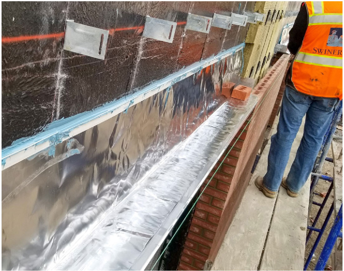
Installation Best Practice
The majority of flashing failures are due to improper installation. Below is a list of best practices.
- Self-adhered membranes should be rolled into place for full adhesion to the substrate
- Substrates must be free of dust, dirt, oils for optimal adhesion
- Prime as required depending on flashing material type
- Seal transition membrane edges
- TWFs must go up the back a min. of 8”, sometimes more depending on detailing
- TWFs must extend beyond the fenestration head by either 6” or the first vertical mortar joint
- Place weep vents a min. of every 24”, rope wicks or weep tubes every 16”
- Do not expose TWFs to UV, instead use copper or stainless steel drip edge
- Use a termination bar if TWFs are not tucked into the backer wall
Conclusion
Cavity wall design has undergone significant code-mandated changes, making previous designs potentially outdated. Components such as air barriers, insulation, and transitions must now meet specific durability and compatibility standards, requiring a reassessment of older design standards in light of modern requirements.

Roy Schauffele
President and Founder
of Division 7 Solutions Inc.

Craig Wetmore
President of York Flashings
As the authors of this article, we have more than 65 years of experience in roofing, cavity wall, and waterproofing design and components, and our sole intent here is to make you aware of today’s choices and changing design environments.


