Your Flashing Authority
Interface Guidelines
Curtain Wall Glazing Assemblies
July 2020
Developed by Transition, Terminations, and Flashings Task Group, Headed up by Group Chairman, Adam Ugliuzza, P.E., CPHC
Introduction
Air leakage and water penetration performance has been established for most building enclosure material and assembly components that are commonly used in the building construction industry. However, air leakage and water penetration performance at the interface of materials and assemblies is often missed or misunderstood. Continuity of a building’s air and water control layer(s) lies heavily on how well the building enclosure components are interfaced. It is critical for the design professional to establish which components of the building enclosure will comprise the building enclosure air and water control layer(s). These components may include, but are not limited to, air barriers, waterproofing (WP), fenestration, roofing, precast and cast-in-place concrete, prefabricated panel/unitized systems, insulation, miscellaneous and structural steel components and more.
The relationship between components and trades that is required to ensure continuity of the building enclosure’s air and water control layer(s) may not be immediately apparent or intuitive if the contract documents are unsuccessful in presenting the building enclosure as a contiguous and cohesive assembly, composed of inter-related parts. Furthermore, if the contract documents fail to clearly represent the building enclosure’s continuous air and water control layer(s) and trade relationships, the related subcontractor’s obligation will be limited to the installation and performance of their material, system or assembly alone. This paper will focus primarily on curtain wall glass glazing systems and the integration with adjacent building enclosure air and water control components.
Background
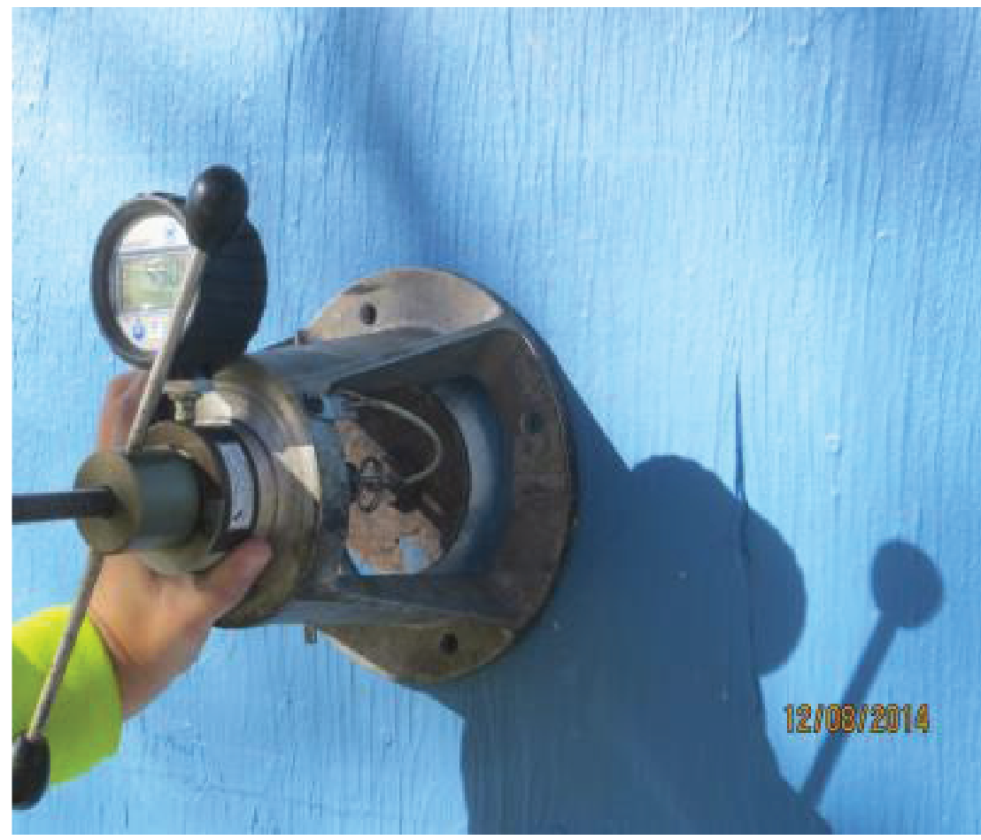
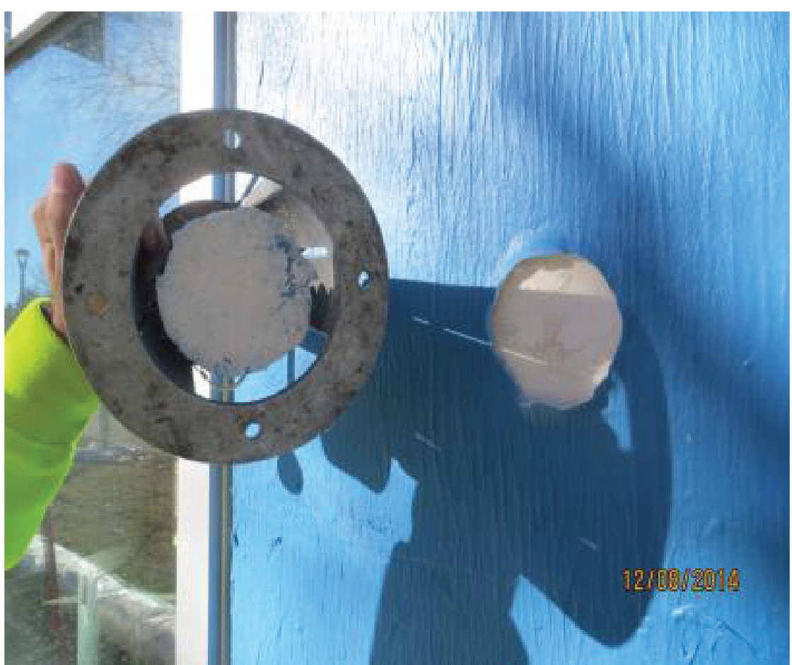
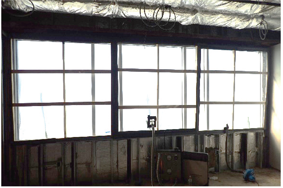
With proper interfacing of the curtain wall to the building enclosure’s air and water control layer(s), the curtain wall assembly and the adjacent enclosure assemblies become compartmentalized. There is a clear delineation of where air and water control layers of each assembly begins and ends, when transitioning across the wall. Conversely, when the marriage of assemblies is not continuous, there is breach that can lead to water penetration, air leakage, energy loss, condensation, and other performance issues. In these cases, it can be difficult to assign responsibility when a failure occurs. Often there is confusion as to what trade is to blame. When evaluated separately, there may not be deficiencies that are leading to the reported failure. Rather, poor interfacing exposed portions of the assemblies, specifically curtain wall, that can not effectively control air or water (reference Figure 1a-c).
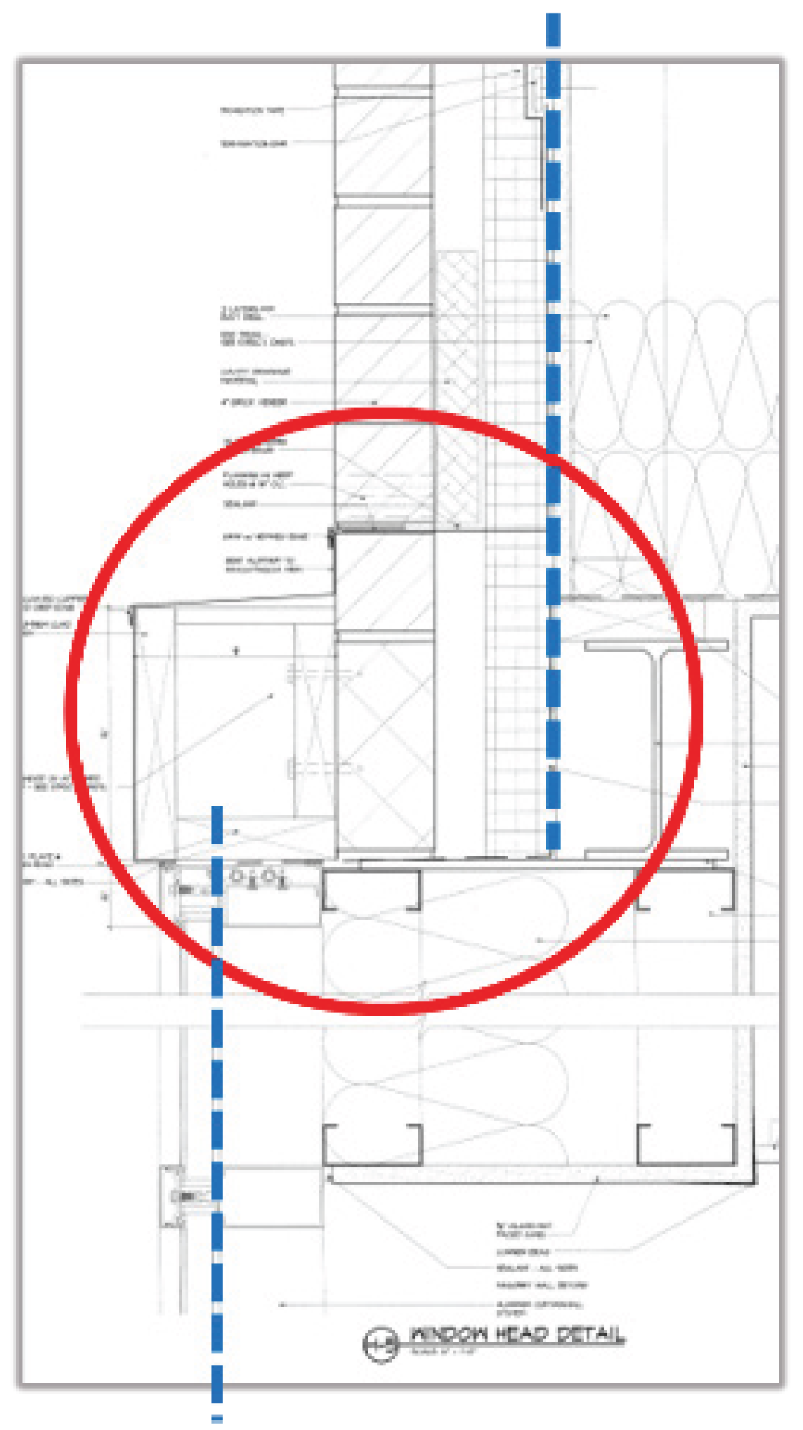
Figure 1a, Failure Investigation
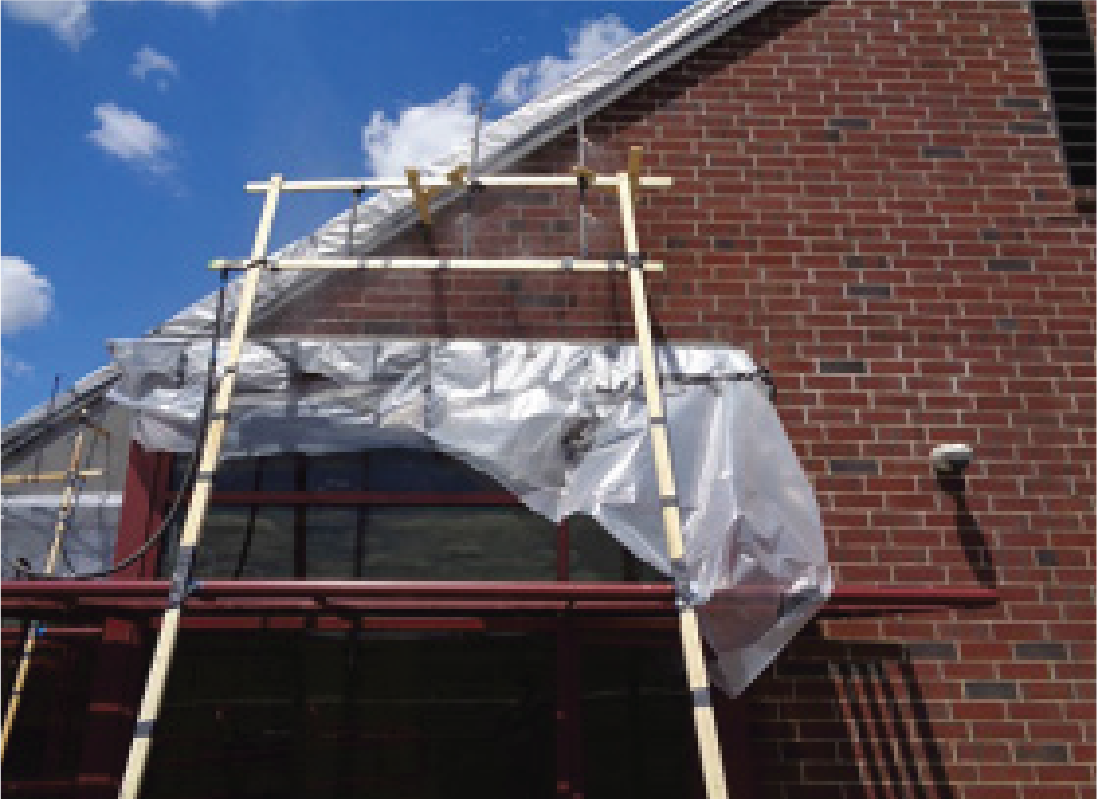
Figure 1b, Failure Investigation

Figure 2, Stick Built Curtain Wall
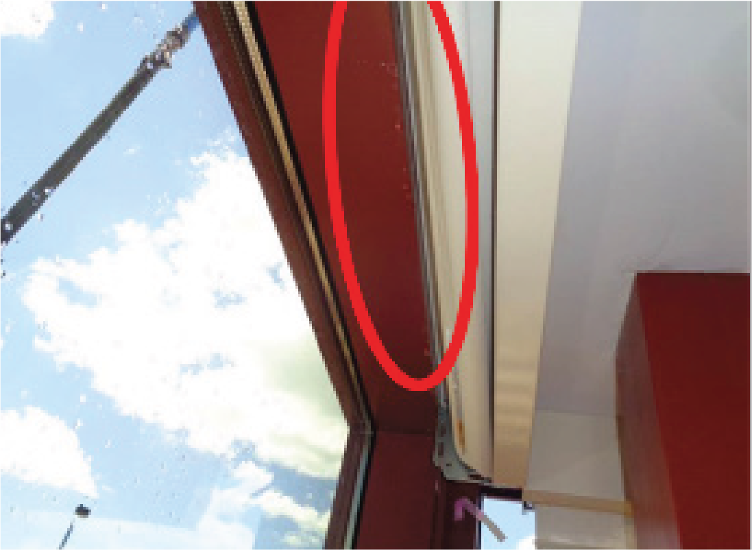
Figure 1c, Failure Investigation
Unitized Curtain Wall
Unitized assemblies help balance the need for rapid close-in, while offering design flexibility, aesthetics, durability, and structural integrity. Architects and building owners are also often looking for single source suppliers that can handle the complete process. Unitized assemblies are very customizable for anchoring depending on the building location and configuration. Unitized assemblies may not be applicable for more complex projects where modulization of the curtain wall assembly is difficult to achieve (reference Figure 3).
Overview
The most common types for curtain wall glass glazing assemblies are stick-built and unitized. Several factors including budget, schedule, complexity, and available job-site staging area must be considered to determine which assembly is appropriate for the project.
Stick Built Curtain Wall
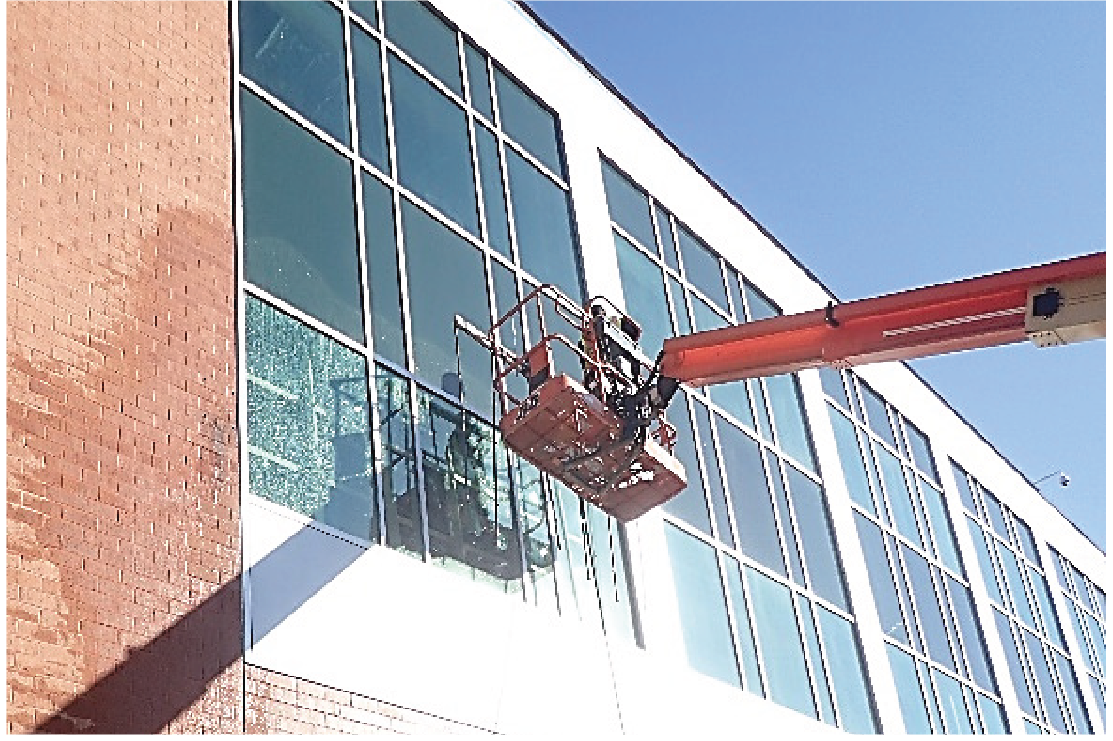
Stick Built assemblies are commonly installed on low-to mid-rise applications, with most installation and glazing done on the job site. For façades with more complex designs and/or shorter product lead times, Stick Built may be an ideal solution. The downside, however, is that more labor is required on the jobsite, fabrication and installation can take longer to complete and jobsite conditions can impact the integrity of the installation and performance. Additionally, more space is required on the jobsite to fabricate and store materials, which is often challenging in urban environments where space is becoming increasingly limited (reference Figure 2).

Figure 3, Unitized Curtain Wall
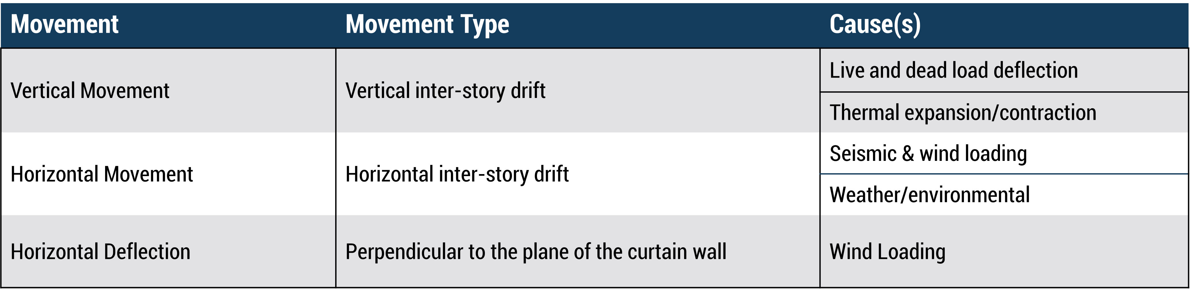
Figure 4, Curtain Wall Movement
Curtain Wall Design Considerations
Movement and Anchorage
Curtain wall assemblies are all designed to accommodate building movement. Weather, environmental factors and a multitude of loading conditions all impose forces on the curtain wall assembly and require the curtain wall to accommodate movement (reference Figure 4, Curtain Wall Movement).
A structural engineer must be involved in the design to ensure curtain wall structural integrity and to provide anticipated movement requirements so that air and water tightness is maintained within the curtain wall assembly and at the perimeter condition where interfacing with adjacent assemblies.
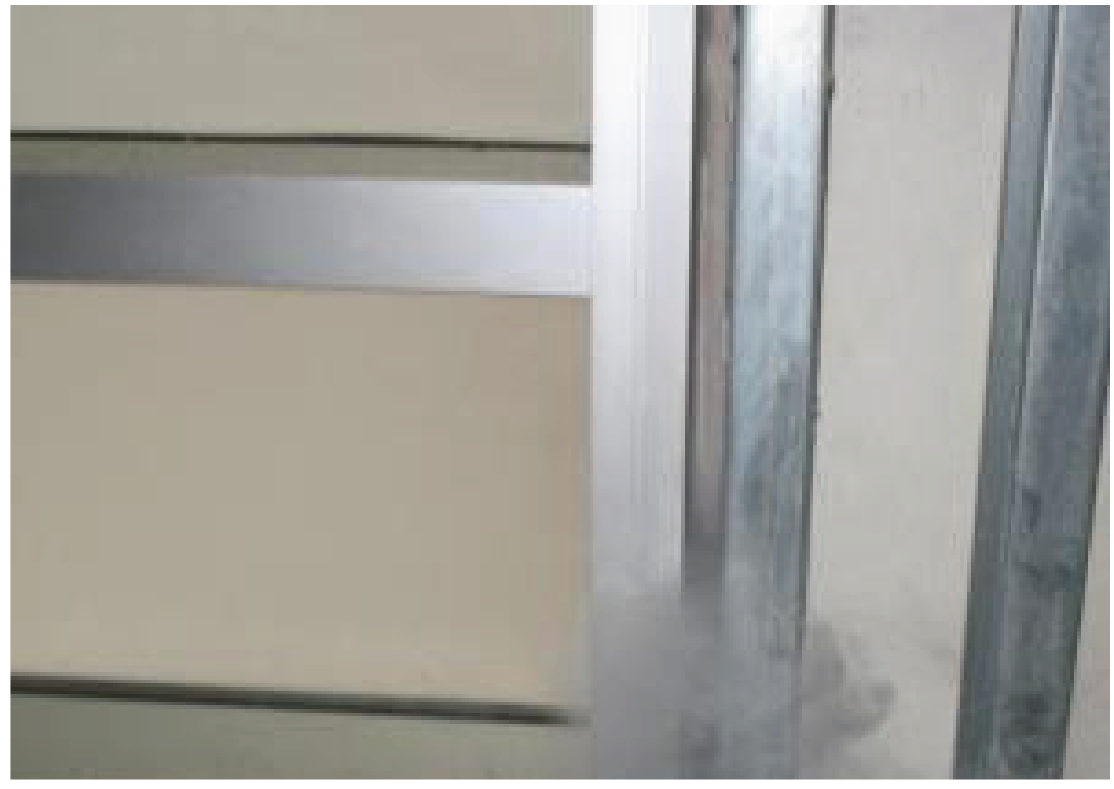
The anchoring method used is based on calculations and the determination of which method is best suited for the application. Stick Built assemblies will accommodate several types of anchoring methods. For Stick Built assemblies these can vary from “F” and “T” anchors or “F” perimeter anchors for sill and head conditions and slab edge/structural member connections for anchorage within the vertical span. Vertical splice connections are commonly employed to transfer load or accommodate movement for taller curtain wall spans or when the vertical mullions cannot be continuous (reference Figure 5, Stick Built Connections).
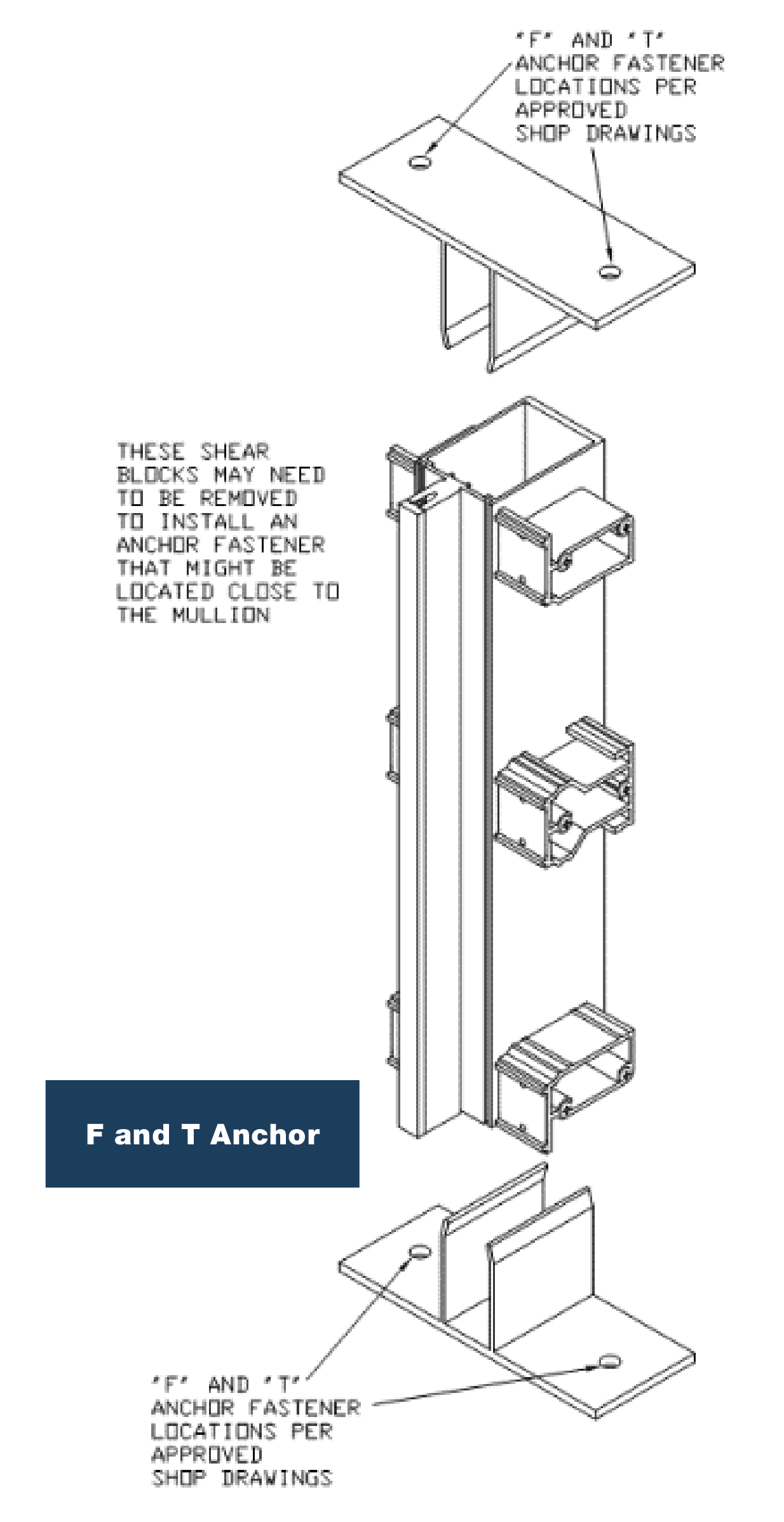
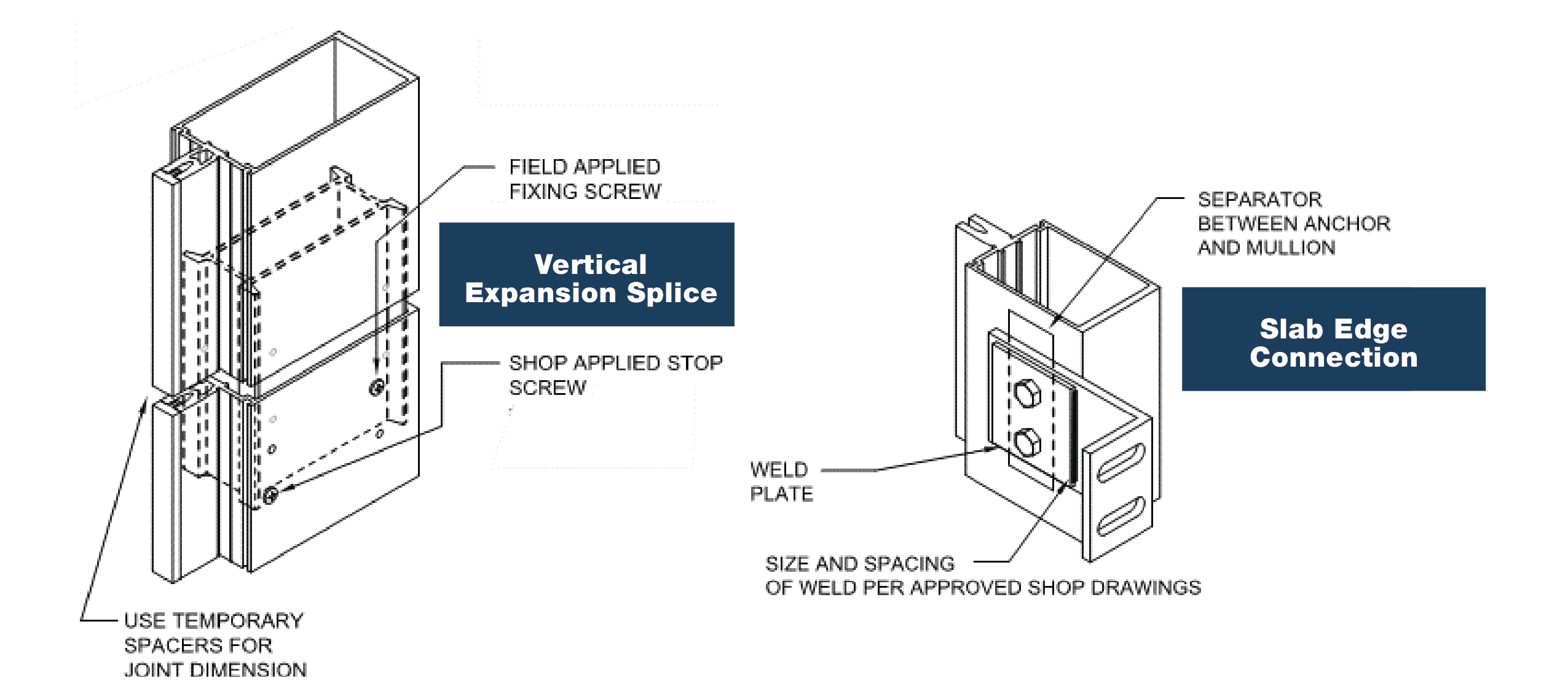
Figure 5, Stick Built Connections
Kawneer 1600 System2 Installation Instructions. Kawneer, Norcross, GA, USA, 2007, pp. 162-971 3 of 12 - 162-971 4 of 12.
Assemblies
Unitized assemblies typically employ a starter sill, sometimes referred to as a “chicken head” to anchor the base of each unit and slab edge/structural member anchor connection near the top of the unit (reference Figure 6, Unitized Connections). Because unitized curtain wall is comprised of modularized units, vertical movement can be accommodated at the horizontal stack joint of each unit as compared to the Stick Built assembly that may require a vertical expansion splice joint.
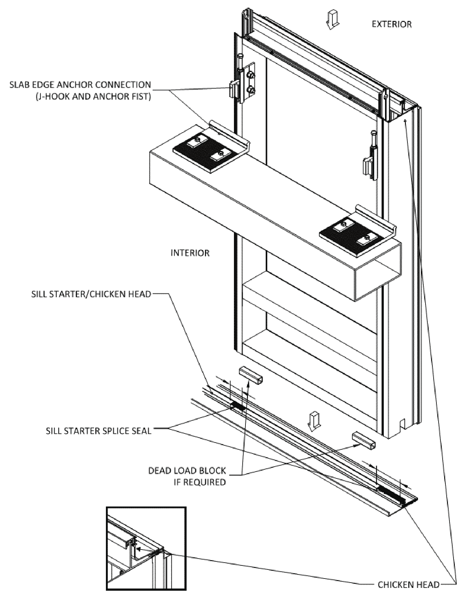
Figure 6, Unitized Connections
YKK AP Unitized Curtain Wall Installation Instructions.
YKK AP America Inc., Austell, GA, USA, 2009.
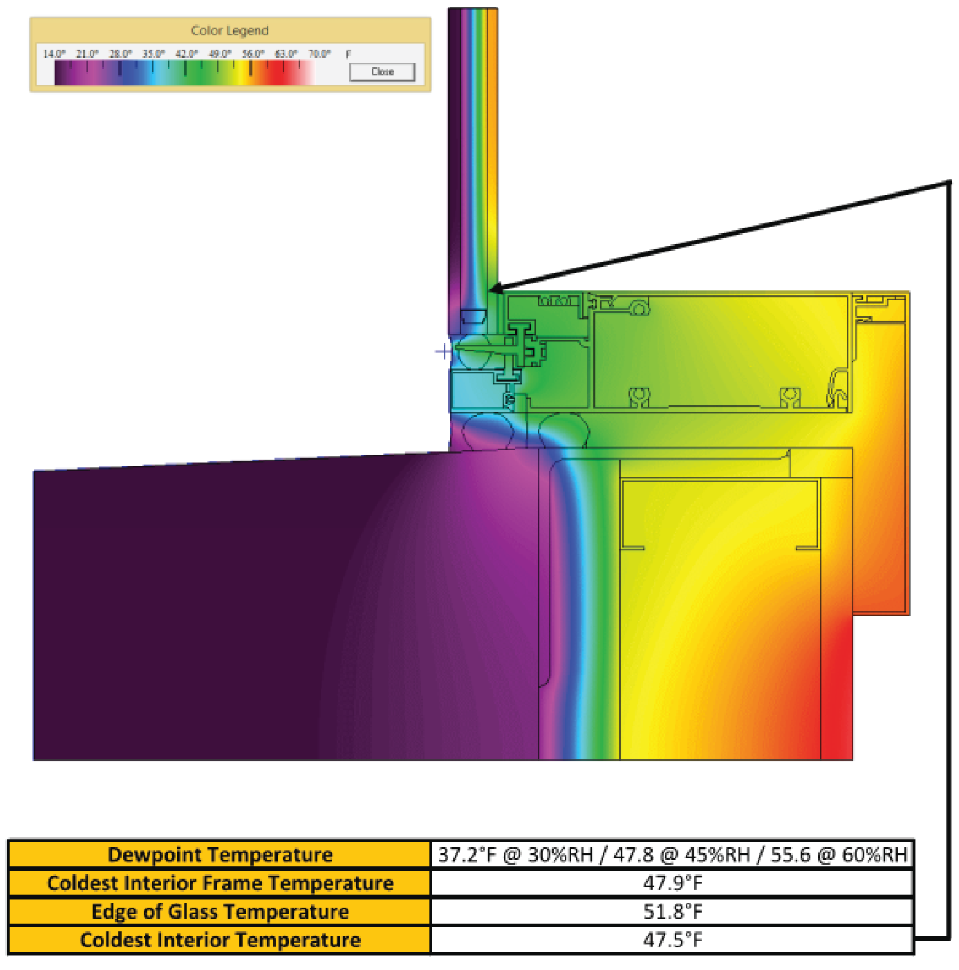
Figure 7, THERM Model
Precast Concrete Opening
Air, Water and Thermal Control
Each assembly typically has a defined plane for air and water tightness. The complexity of the noted assemblies may require the plane to jog inward and/or outward to maintain continuity when transitioning to different materials that make up the assembly. Understanding the location of this plane, specifically at the perimeter condition, is critical to interfacing with adjacent building enclosure components to achieve continuous air and water control. Consulting the curtain wall manufacturer or reviewing product test reports are usually the easiest way to identify the plane of air and water tightness and location of the primary perimeter seal. Consideration must also be given to not negate the function of thermal separator or thermal break materials that are typically required for thermal performance of the curtain wall assembly; this is typically addressed when sealing the curtain wall assembly at the plane of air and water tightness. The curtain wall alignment with adjacent opaque wall assembly thermal control (insulation) must also be considered. Generally, it is best practice to align the insulated glass unit (IGU) with the opaque wall insulation; however, thermal modeling software, like THERM (reference Figure 7), is recommended to review each project condition to better mitigate thermal losses.
Drainage Accommodation
The drainage strategy of the assembly can be easily overlooked. Like understanding the plane of air and water tightness of the assembly, drainage of the assembly is also key. There are two types of curtain wall assemblies, drainage vs. barrier assemblies. Drainage assemblies allow some water to migrate past the exterior surface of the wall to a continuous interior drainage plane, where it is collected and drained back to the exterior utilizing integrated channels and weeps, as well as flashings and other accessories, to collect and drain water. When interfacing with adjacent assemblies, be sure that the curtain wall assembly weeps or weep channels are not sealed, blocked or restricted from properly weeping. In contrast to drainage assemblies, barrier wall assemblies are designed to prevent water from penetrating the wall by employing an exterior face seal. Barrier wall assemblies rely on the exterior surface of the wall and sealant joints to remain air and watertight.
Construction Sequence
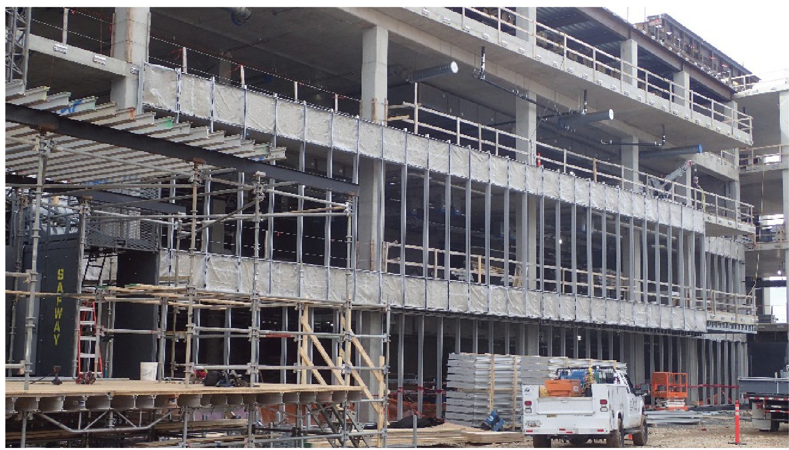
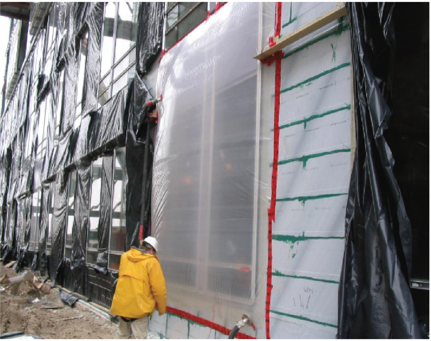
The sequence of construction can vary; regardless, it is critical that the curtain wall glazing assembly is continuously sealed to the surrounding building enclosure air and water control layer(s). Best practice is that the curtain wall glazing assembly is installed prior to the installation of cladding to allow uninhibited access to the critical seals. This also allows the curtain wall glazing assembly to be field tested when all adjacent air and water control layers are exposed, making it easier to diagnose and correct issues. Further, the building is dried in quicker, mitigating the need for temporary tarping; this methodology can help to compress construction schedules as building interiors can be installed simultaneous to exterior cladding (reference Figure 9).
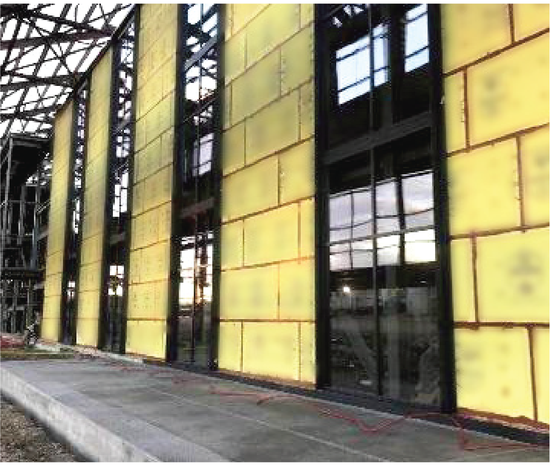
Figure 9, Construction Sequencing
Building Air and Water Control Layers Complete prior
to Wall Cladding Installation
Interface Coordination
Chemical and Adhesive Compatibility of Materials
To create an air and watertight interface between the wall and curtain wall glazing assemblies, materials must be used that are both chemically and adhesively compatible. Sealants, self-adhered and fluid applied flashing membranes, engineered transition membranes (ETAs), etc. can all be used at curtain wall openings to seal the perimeter condition; it is critical that the construction team verify that the project specific combination of materials can work together, especially those sourced from different manufactures.
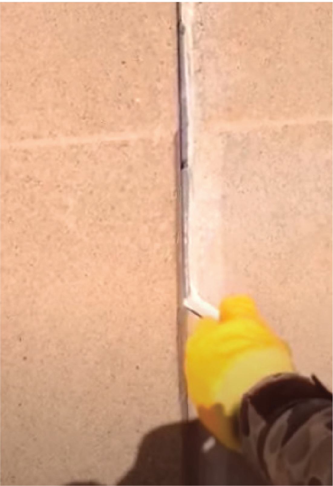
- Sealant Joints – Sealant joints are typically an hour-glass shape formed by tooling the sealant against backer rod or bond breaker tape with a knife. Use of sealant joints is further explained in ASTM C920 which outlines different uses, applications, movement classes, and a variety of other items relative to “Performance Sealants”.
- Flashing Membranes and Pre-cured Silicone Sheet Extrusions - Flashing membranes can be offered in self-adhered sheet or fluid applied options. These membranes and pre-cured silicone sheets include properties such as elongation that accommodates building and curtain wall movement, tear resistance and resistance to flex cracking and abrasions.
For chemical compatibility, request letters from the manufactures of the materials which will be in contact with each other. For adhesion, field testing is required unless the manufacturers have already performed the testing. Note that the manufacturer laboratory testing typically involves sourcing and shipping the test materials that can delay the project. When reviewing, it is common practice for the responsibility of determining chemical and adhesive compatibility be of the manufacturer of the material that is lapping or adhering to an installed material. Consult the manufacturer on the recommended field adhesion test method applicable for the project. Also reference the Quality Assurance (QA)/Quality Control (QC) Requirement Checklist section in this guideline paper that includes industry standard test methods for adhesion.
Preconstruction planning is the best approach to mitigating issues with chemical and adhesive compatibility; the construction team should consider implementing a compatibility matrix to review interfacing materials before installation in the field. Minimizing the number of manufacturers supplying products for a project can also help mitigate issues with verifying chemical and adhesive compatibility, as product manufacturers are generally more equipped to respond to material interface compatibility concerns within their respective product lines.
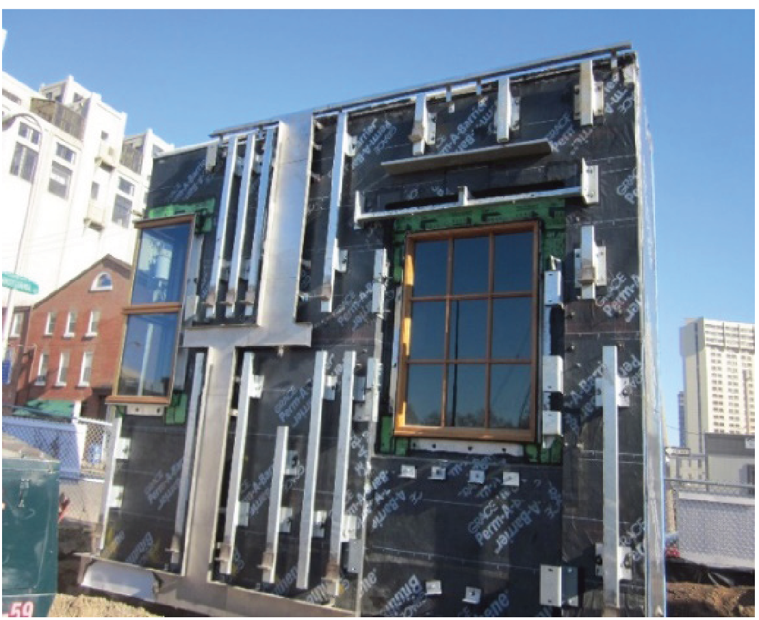
Conceptual Interface
The plane of air and water tightness of each component must be understood to ensure proper integration of components and ultimately that a continuous air and water control boundary for the building is achieved. The conceptual detail provided identifies the plane of air and water tightness and integration of the curtain wall glazing assembly at an opening condition. The detail below is representative of a typical “pressure wall” type curtain wall glazing assembly.
The example below does not represent all curtain wall glazing assemblies; the plane of air and water tightness assembly may vary. The designer and installer must review the curtain wall assembly design, product data and test reports to fully understand the plane of air and water tightness for the specified curtain wall assembly. This is the foundation for determining the location for the curtain wall assembly primary seal and tie-in to the adjacent building enclosure assembly air and water control layers.
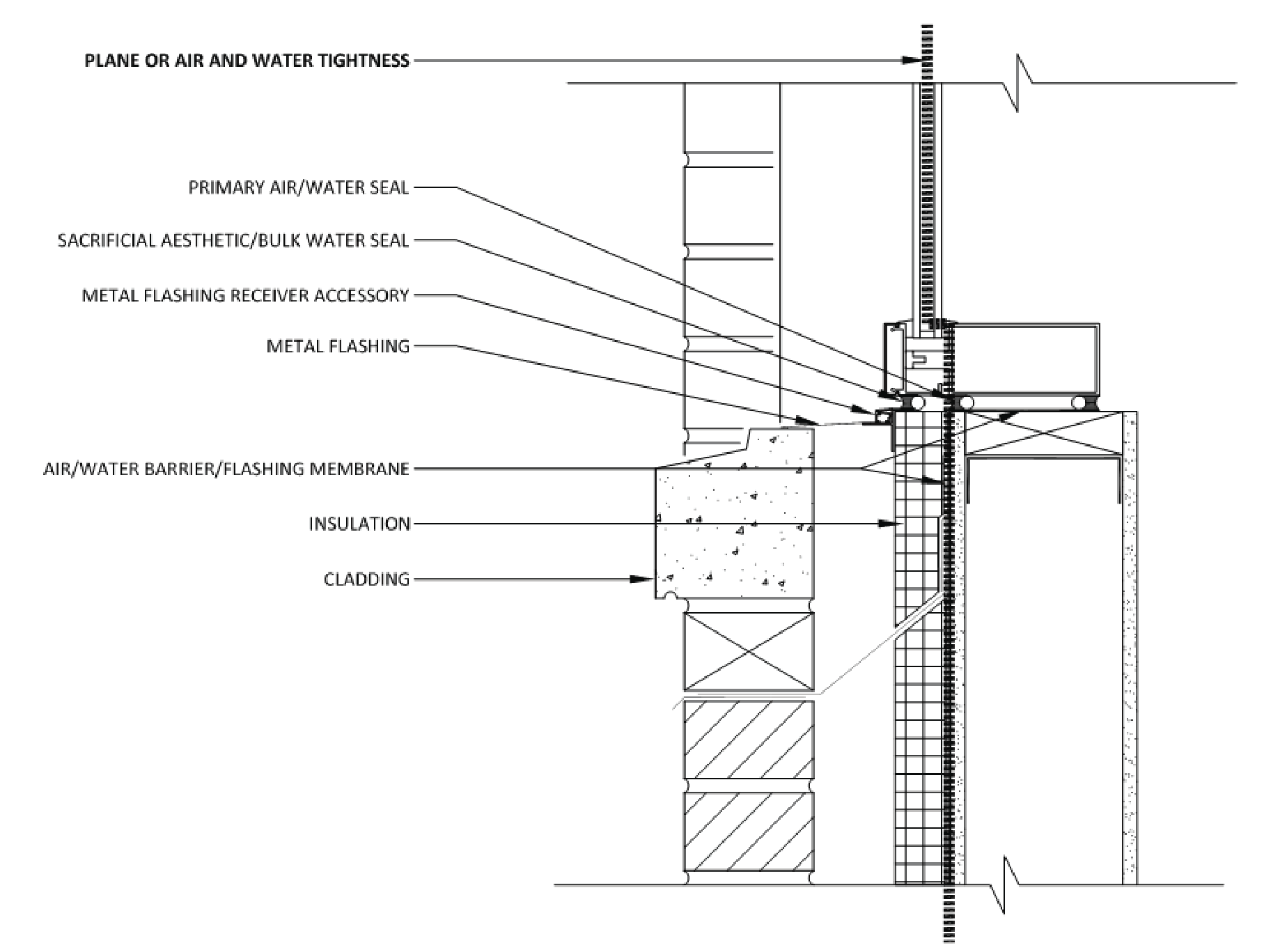
Figure 10, Conceptual Detail
Warranty Considerations
Curtain wall manufacturer limited warranties typically offer no protection against improper installation or failure to integrate with the air and water control layer(s). The warranty of installation, including labor to replace faulty or damaged parts of the CW, would have to be covered under the trade contractor’s warranty that is typically less than two (2) years. An example for a manufacturer material warranty has been provided below.
Warranty provides, in part:
- Covers only products and components supplied by manufacturer
- Does not cover incompatibility with other glazing or installation materials; improper building design, specifications or construction; excessive, localized or asymmetrical building movements; damage caused by water entry from sources other than manufacturer’s materials; field fabrication, finishing, or forming; damages caused by any chemicals used on or around the product
- LABOR AND EQUIPMENT, TO REMOVE AND/OR REPLACE MATERIAL OR COMPONENTS DETERMINED BY MANUFACTURER TO BE DEFECTIVE, IS NOT INCLUDED.
- Repair of thermal barrier dry shrinkage resulting in leakage will be limited to the repairs described in the AAMA Technical Bulletin 91-1.
- Final installation adjustments, and/or any other adjustments after installation, are not the responsibility of manufacturer, and are not covered by this warranty. Improper layout or installation voids this warranty.
- In no event will any other warranty terms apply to the sale of manufacturer products, including but not limited to, the project specifications, general conditions, and/or other bid or contract documents.
These qualifications show the critical importance of seeing to it that a proper interface detail is developed, and that it is properly executed. The specifications must clearly define shop drawing requirements relating to the curtain wall / air barrier connection, so that the contracting documents will clearly identify scope of work to develop and perform the detail. Also, consider specification of the ABAA Quality Assurance Program for the perimeter air barrier installation. With ABAA-trained companies and employees, the audit and observation functions within that program will help ensure proper execution of this critical building enclosure interface.
Specification Recommendations
Often, individual building enclosure material and assembly specification sections fail to acknowledge the relationship or interface between adjacent components. These relationships should be indicated in the design drawings for consideration by general contractors and subcontractors in delineating scope, defining the extent of a warrantable systems and coordination and sequencing of trades in the field.
Proper specification coordination and cross referencing, in association with the building air and water control components, includes referencing related specification sections, identification of pre-construction meeting participants and meeting content, clearly defining shop drawing requirements related to project specific detailing and identification of all interfacing systems (with designation of those both in-contract and NIC) and mock-up consideration(s). In addition to the specification coordination and cross referencing requirements mentioned above, it is recommended to include a Division 01 specification (e.g. Building Enclosure Commissioning Section (019115) or other) that can holistically define building air and water control and collectively locate laboratory and field performance testing requirements. Individual sections often include performance testing requirements for the specified material or system component, but do not address whole building performance requirements that mandates a continuous interface between all components.
Examples of Building Enclosure Component Inter-Relationships:
- Glazer/Roofer/Mason may be responsible for individual water resistant barrier (WRB) component installation
- Concrete/masonry subcontractor responsible for substrate conditions where WRB is applied
- Waterproofing (WP) and WRB may all tie-in and require specific sequencing to achieve continuity
- Mason’s installation of through wall flashing (TWF) tie-into WRB, compatibility considerations
- WRB and WP proprietary mastics interfacing with other sealants etc. compatibility
- Coordination of WRB laps dimensions and interface with fenestration assembly sealant joints
QA/QC Requirement Checklist
Architectural Drawings and Project Specification Review
- Recommend review of initial design drawings by building enclosure consultant.
- Confirm consistent tie-in of air and water control layers at sill, jamb and head conditions. Opening may require additional materials (e.g. wood blocking, metal collar, flashing receiver etc.) to extend opening to receive primary seal of the curtain wall. This adds cost that may not accounted for.
- Confirm curtain wall assembly and associated opening allow for movement, and perimeter conditions can accommodate the movement.
- Confirm project specification includes project specific shop drawing requirements, including tie-in to perimeter air and water control layers.
- Confirm project specifications require on-site mock-up for review.
- Confirm project specification includes testing.
- Consider laboratory testing, especially if custom curtain wall assembly.
ASTM E330-14, Standard Test Method for Structural Performance of Exterior Windows, Doors, Skylights and Curtain Walls by Uniform Static Air Pressure Difference
ASTM E283-04 (2019), Standard Test Method for Determining the Rate of Air Leakage Through Exterior Windows, Curtain Walls, and Doors Under Specified Pressure Differences Across the Specimen
ASTM E331-00 (2016), Standard Test Method for Water Penetration of Exterior Windows, Skylights, Doors, and Curtain Walls by Uniform Static Air Pressure Difference.
AAMA 501.1-17, Standard Test Method for Water Penetration of Windows, Curtain Walls, and Doors using Dynamic Pressure
AAMA 501.4-18, Recommended Static Testing Method for Evaluating Curtain Wall and Storefront Systems Subjected to Seismic and Wind Induced Inter-Story Drift
AAMA 501.5-07, Test Method for Thermal Cycling of Exterior Walls
AAMA 501.7-17, Recommended Static Testing Method for Evaluating Windows, Window Wall, Curtain Wall and Storefront Systems Subjected to Seismic and Vertical Inter-Story Drift Movement
Submittals
- Manufacturers’ installation instructions.
- Manufacturers’ letter of compatibility.
- Manufacturers’ Warranty
- Product Test Reports
- Define scope of work
- Coordinated shop drawings
- Clearly depict/name products and relationships in detailing in shop drawings
Pre-Construction Meeting
- Review submittals
- Review installation
- Review construction sequencing
- Review construction quality control checklists
- Installation sequencing and responsibility
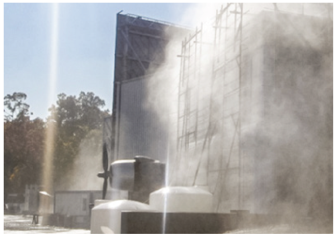
Figure 11, Laboratory Performance
Mock-up Testing, AAMA 501.1
Observation/Testing Including Interface
Documentation of Observations

Onsite Performance Mock-ups
Common Field Testing
AAMA 501.1-17, Standard Test Method for Water Penetration of Windows, Curtain Walls and Doors Using Dynamic Pressure
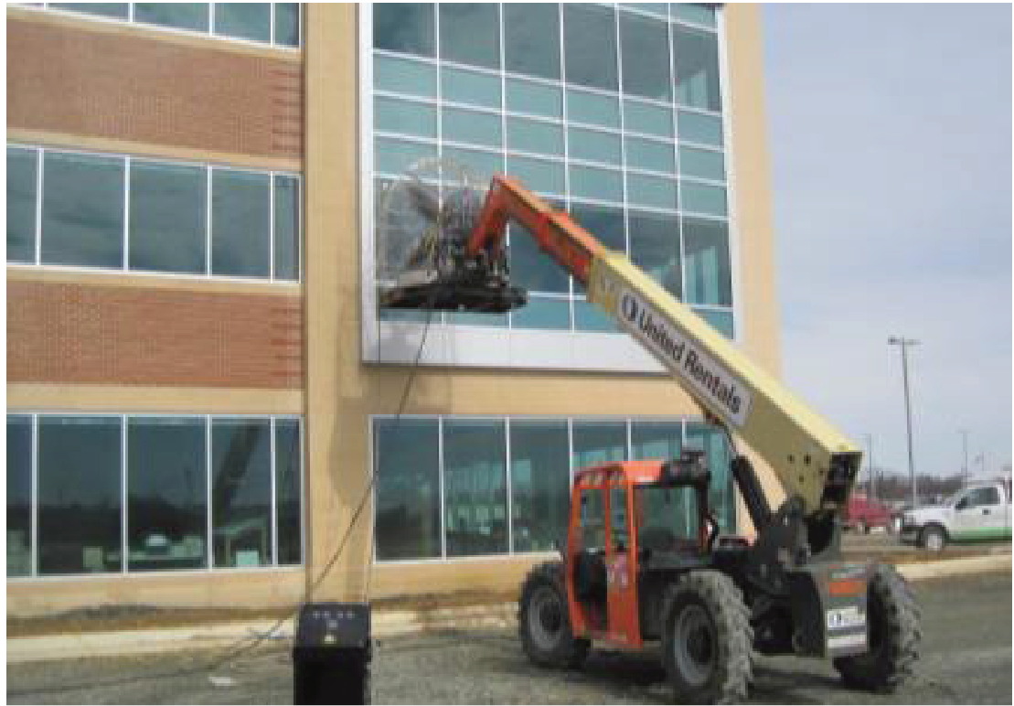
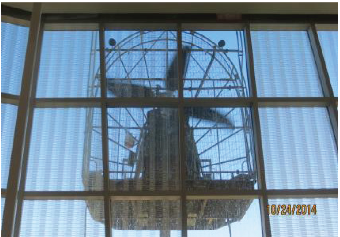
AAMA 501.2-15, Quality Assurance and Diagnostic Water Leakage Field Check of Installed Storefronts, Curtain Walls and Sloped Glazing Systems
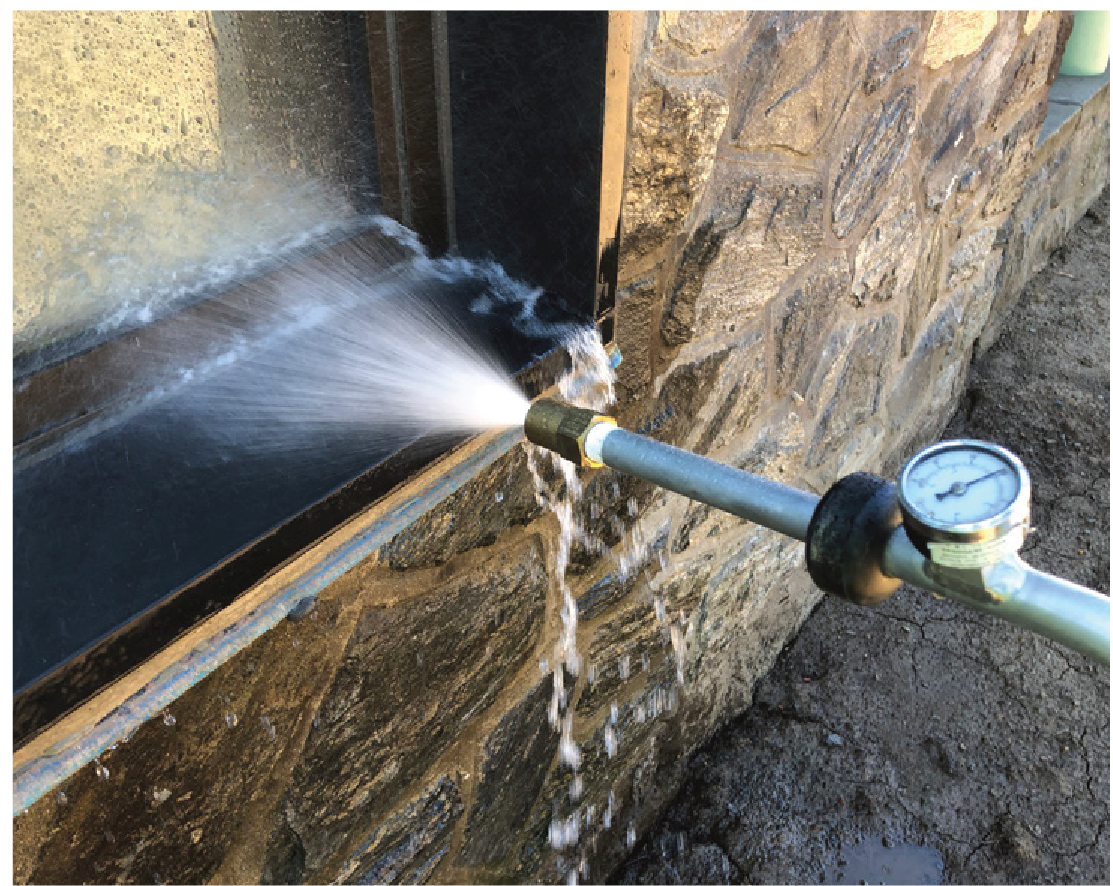
ASTM E783, Standard Test Method for Field Measurement of Air Leakage Through Installed Exterior Windows and Doors
ASTM E1105, Standard Test Method for Field Determination of Water Penetration of Installed Exterior Windows, Skylights, Doors and Curtain Walls, by Uniform or Cyclic Static Air Pressure Difference
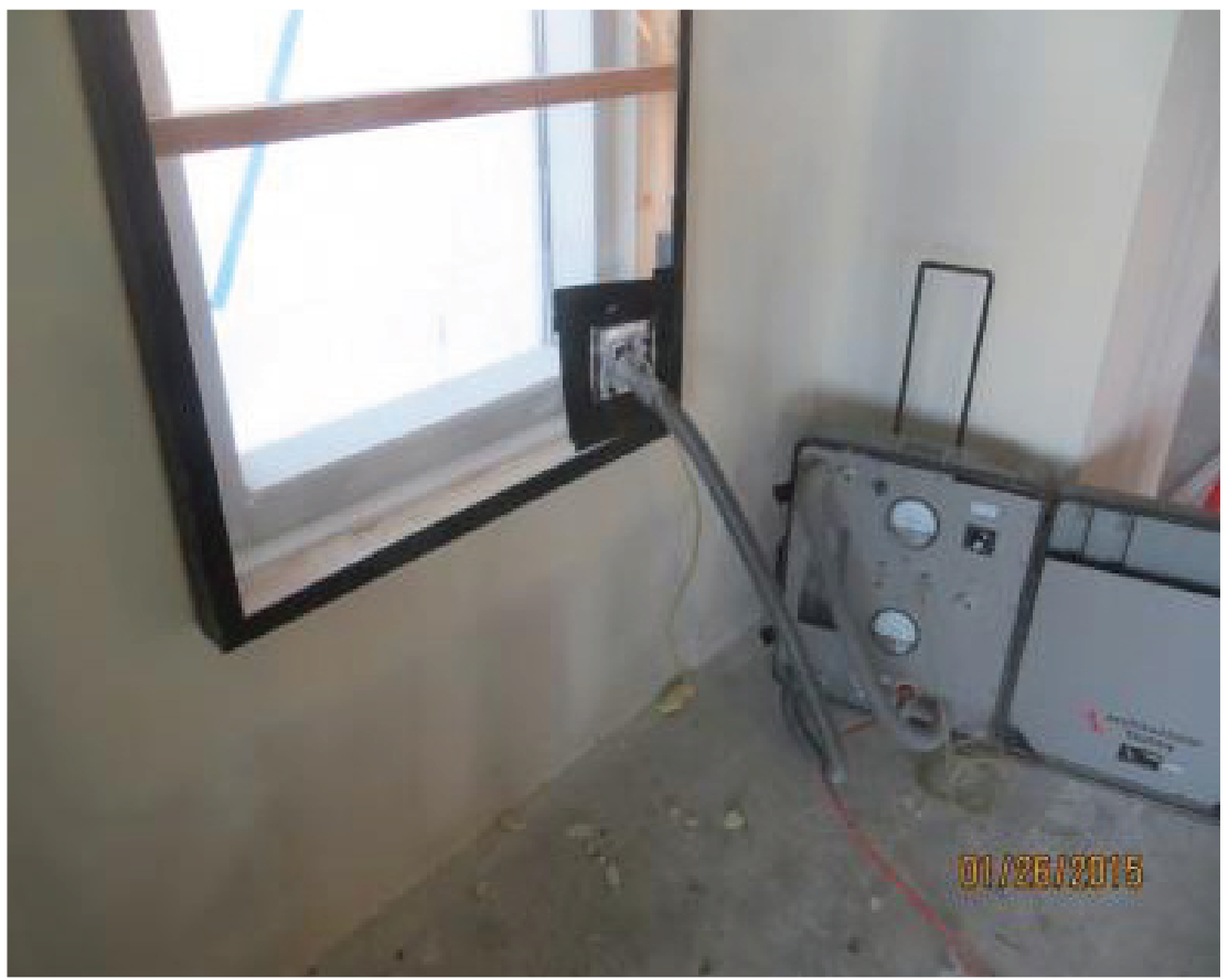
ASTM E1186, Standard Practices for Air Leakage Site Detection in Building Envelopes and Air Barrier Systems
ASTM E1186, Smoke Tracer
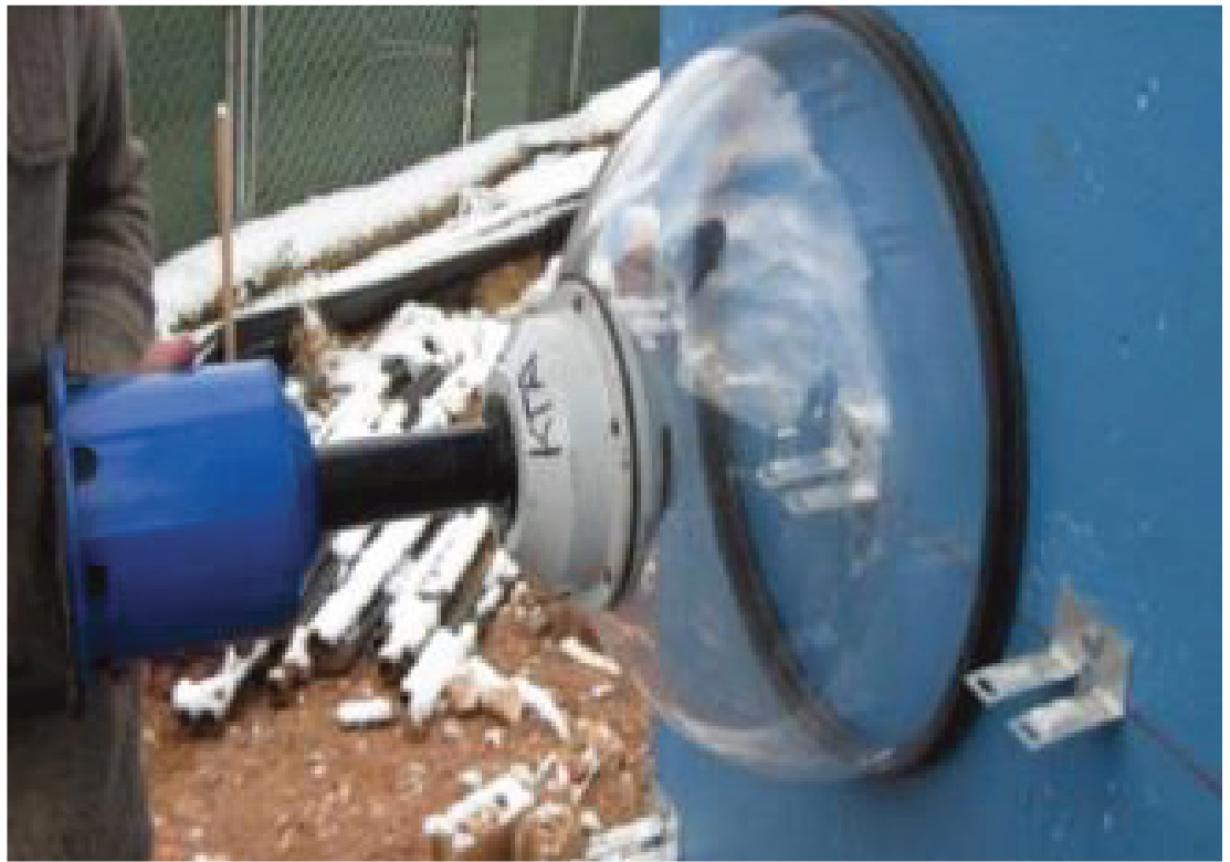
ASTM E1186, Bubble Gun
ASTM E1186, Smoke Tracer

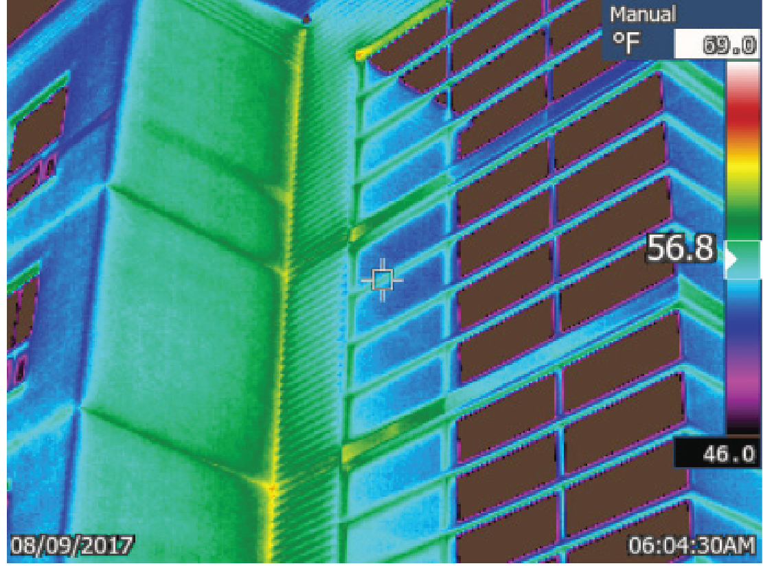
Infrared Scanning
ASTM C1521, Standard Practice for Evaluating Adhesion of Installed Weatherproofing Sealant Joints
ABAA T0002 “Standard Test Method for Pull-Off Strength of Adhered Air and Water Resistive Barriers Using an Adhesion Tester”